


 English

News
Thu 08 , 2026
Warpage is one of the most common injection molding defects affecting automotive plastic parts. It occurs when different areas of a molded component shrink or cool at different rates, causing the finished part to bend, twist, or deviate from its intended geometry. For automotive components, even a relatively small amount of deformation can create assembly problems, uneven gaps, or visible surface distortion.
In automotive injection molding, warpage is rarely caused by one factor alone. Material shrinkage, wall thickness, mold temperature, cooling efficiency, injection pressure, holding pressure, gate location, and overall injection mold Design can all contribute to the final result.
Understanding these factors is essential for producing stable plastic injection parts, especially large or complex automotive components.
During the injection molding process, molten plastic enters the mold cavity, fills the part, undergoes packing, and then cools and solidifies.
Plastic naturally contracts as its temperature decreases. If every area of the part cooled and shrank at exactly the same rate, warpage would be much easier to control.
In real production, however, different sections of an automotive component often have different wall thicknesses, cooling conditions, flow orientations, and packing pressures.
This creates uneven shrinkage.
For example, a thick rib may remain hot for longer than a thin wall. One side of a component may cool faster because it is closer to a cooling channel, while another area remains hotter. These differences generate internal stresses that can eventually deform the part after ejection.
This is why injection molding warpage needs to be addressed at both the mold design and process stages.
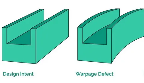
Material shrinkage is one of the fundamental causes of warpage.
Thermoplastics contract as they cool from the molten state to room temperature. Different materials have different shrinkage characteristics, and reinforced materials can behave differently from unfilled polymers.
In automotive applications, material selection should therefore be considered before the plastic injection mold is designed.
For example, a material such as PP may have different shrinkage behavior from a reinforced PP grade. If the material specification changes after mold design has already been completed, the molding process and dimensional performance may also change.
For this reason, the mold designer needs accurate material data before determining critical dimensions, cooling requirements, and process conditions.
Large differences in wall thickness are another common cause of warpage.
Thicker areas contain more material and generally require more time to cool. Thin sections can solidify earlier while thicker sections remain hot.
As the component continues cooling, these areas may shrink differently.
Automotive components frequently contain ribs, bosses, mounting structures, clips, and reinforcing sections. If these features are significantly thicker than the surrounding wall, they can create localized shrinkage and deformation.
A well-developed injection mold design should therefore consider wall-thickness distribution during the product development stage.
Uniform wall thickness is not always possible because of functional requirements, but abrupt changes should be minimized where practical.
The cooling system is one of the most important factors in controlling injection molding warpage.
After the cavity is filled and packed, heat must be removed from the molded part. If cooling is uneven, different areas can reach the ejection temperature at different rates.
For example, one side of a large automotive component may be cooled effectively while another side remains significantly hotter.
The result can be differential shrinkage and deformation.
Cooling channels should therefore be designed according to the actual product geometry rather than simply arranged around the mold block.
Channel diameter, spacing, depth, layout, and distance from the cavity surface all influence cooling performance.
For complex automotive injection molding projects, cooling design should be considered together with wall thickness, material behavior, and expected cycle time.
Mold temperature also affects shrinkage and part deformation.
A mold that is too cold may cause premature solidification and uneven filling, while excessive mold temperature can increase cooling time and influence dimensional shrinkage.
More importantly, temperature differences between different areas of the mold can create inconsistent cooling conditions.
Maintaining a controlled and reasonably uniform mold temperature can help reduce dimensional variation.
In plastic injection molding, mold temperature should therefore be treated as part of the overall process window rather than as an isolated machine setting.
Injection speed affects how molten plastic travels through the cavity.
If the filling pattern is unbalanced, different areas of the part may experience different shear conditions, pressures, and molecular orientations.
For some materials, this flow orientation can contribute to anisotropic shrinkage after molding.
The effect can become more noticeable in large automotive parts with long flow paths.
This is why the relationship between gate location, runner design, injection speed, and cavity geometry needs to be considered during injection mold design.
Increasing injection speed does not automatically solve filling problems. In some situations, it may reduce short-shot risk while increasing other molding issues.
The goal is to establish a stable filling profile that provides consistent material distribution throughout the cavity.
Packing plays an important role in controlling shrinkage.
After the cavity is filled, holding pressure is applied to compensate for the material's volume reduction as it begins to cool.
If holding pressure is too low or holding time is too short, some areas may not receive sufficient packing. This can increase shrinkage and contribute to dimensional instability.
However, simply increasing holding pressure indefinitely is not a reliable solution.
Once the gate has frozen, additional holding pressure may have limited influence on the cavity. Excessive packing can also increase internal stress or affect dimensions.
The appropriate holding-pressure profile therefore depends on the material, gate design, part geometry, and molding conditions.
Gate location has a direct relationship with material flow and packing.
A poorly positioned gate can create an uneven filling pattern, long flow paths, unbalanced pressure distribution, or unfavorable weld-line locations.
For large automotive plastic injection parts, gate design should consider both appearance and dimensional stability.
A gate placed too far from a critical area may make it difficult to maintain adequate packing pressure at that location.
Multiple gates may improve filling for certain large components, but they also introduce additional flow fronts and potential weld-line locations.
Gate selection should therefore be based on the actual geometry and molding requirements rather than a fixed standard.
The basic structure of the mold can also influence the dimensional accuracy of the molded part.
Poor alignment between the cavity and core may create uneven wall thickness or mismatch. Inadequate support of inserts can allow movement during injection, while unsuitable ejector placement may introduce deformation during demolding.
For this reason, injection mold design needs to consider not only how the plastic fills the cavity but also how the mold supports the part throughout injection, cooling, and ejection.
For complex automotive Tooling, mold rigidity and component alignment become particularly important as injection pressure increases.
A component may appear acceptable inside the mold but become distorted during ejection.
At the moment of ejection, the plastic part may still retain heat and may not yet have developed sufficient rigidity.
If ejector pins are poorly distributed or concentrated in certain areas, excessive local force can deform the part.
Deep ribs, clips, undercuts, and large flat surfaces can make ejection more challenging.
A suitable ejection system should distribute force appropriately while providing enough draft for reliable demolding.
This is another reason why ejection needs to be considered during the early plastic injection mold design stage.
Reducing warpage usually requires a combination of product design optimization, mold modification, and process adjustment.
Where possible, avoid sudden transitions between thick and thin sections. Ribs should generally be designed to provide structural support without creating excessive local material accumulation.
Cooling channels should be positioned to provide more uniform heat removal across the cavity.
For large automotive components, localized cooling problems can have a significant effect on final dimensions.
The gate should provide a suitable filling and packing pattern while considering appearance requirements and critical dimensions.
Holding pressure and holding time should be sufficient to compensate for material shrinkage without creating unnecessary internal stress.
Injection speed, pressure, melt temperature, mold temperature, holding pressure, and cooling time should be optimized together.
Changing one parameter without considering the others can sometimes move the problem rather than solve it.
For complex automotive injection molding projects, simulation can be useful before manufacturing the mold.
Mold flow analysis can help engineers evaluate filling patterns, pressure distribution, cooling behavior, shrinkage, and potential warpage.
This provides an opportunity to identify potential problems before steel is cut.
Simulation does not eliminate the need for physical trial molding, but it can reduce unnecessary design iterations and provide useful information for optimizing the injection mold design.
For large or highly complex automotive components, combining simulation with actual trial results can provide a more reliable basis for process optimization.
During a mold trial, the molded part should be evaluated against the approved drawing and quality requirements.
Inspection may include:
Overall length and width
Flatness
Critical mounting dimensions
Hole and clip positions
Mating surfaces
Part thickness
Visual deformation
Assembly fit
For automotive components, dimensional inspection should not be separated from assembly requirements.
A component may remain within a general dimensional tolerance while still producing an excessive gap when assembled with another part.
Therefore, the definition of acceptable warpage should be connected to the actual function of the component.
Solving warpage during the first mold trial is only part of the process.
During mass production, changes in material batches, machine conditions, mold temperature, cooling efficiency, cycle time, and mold wear can gradually affect part dimensions.
This makes injection molding quality control important throughout production.
Regular dimensional inspection can help identify trends before they develop into large-scale quality problems.
Mold maintenance should also include checking cooling channels, ejector systems, sliders, gates, inserts, and cavity surfaces.
A stable mold combined with a controlled process provides a better foundation for consistent injection molding parts.
Injection molding warpage is not normally caused by one machine parameter.
It is the result of the interaction between:
Material → Product Design → Mold Design → Material Flow → Packing → Cooling → Ejection → Process Control
Changing only the injection pressure may not solve a problem caused by uneven cooling. Increasing cooling time may not correct deformation caused by poor gate placement. Likewise, changing the mold temperature may have limited effect if the product itself contains large differences in wall thickness.
A systematic approach is therefore more effective.
For automotive plastic components, the most reliable solution is to identify the root cause, determine whether it originates from the product, mold, material, or process, and then make targeted adjustments.
Warpage control begins before the first part is molded.
The geometry of the automotive component determines the mold structure. The material determines part shrinkage and flow behavior. The mold controls filling, packing, cooling, and ejection. Finally, the injection molding process parameters determine how these factors interact during production.
For this reason, automotive injection molding requires close coordination between product design, plastic injection mold development, mold manufacturing, trial molding, and production quality control.
Understanding the causes of injection molding warpage not only helps improve individual parts but also helps reduce mold modifications, production instability, and dimensional problems during mass production.
We attach great importance to the customers' demands for product quality and rapid production.
We always believe that meeting the customers' needs is the realization of our value!