


 English

Products
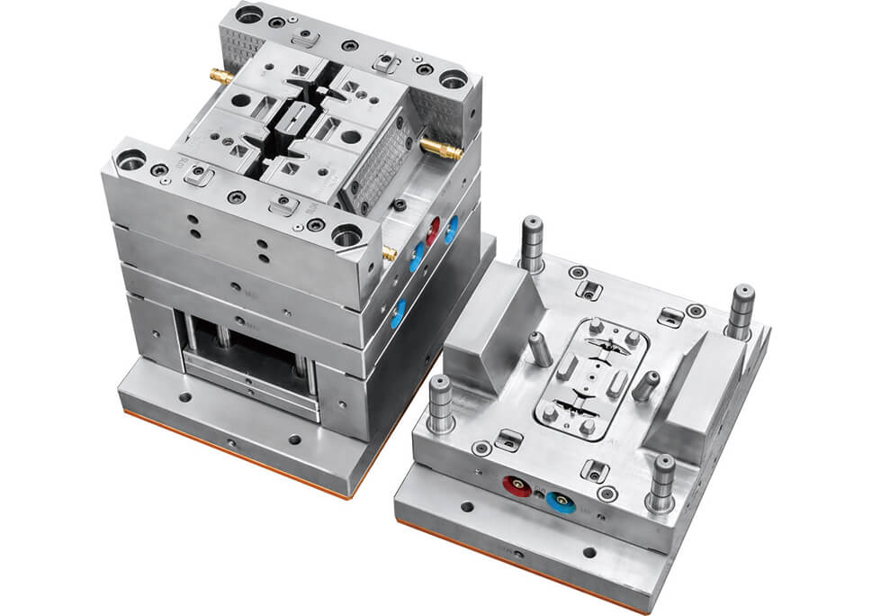
This Support Frame is manufactured using PA66-GF30 injection molding with an overmolding-oriented tooling configuration. The mold uses 2 cavities, a cold runner with sub gates, and 1.2343 cavity steel hardened to HRC 48–52.
The tooling is Designed according to HASCO standards and is identified as an overmolding mold. This configuration places particular emphasis on insert positioning, cavity accuracy, material flow, dimensional stability, and repeatable molding conditions.
A Support Frame is generally a functional structural component used to support, locate, retain, or connect other components within an assembly. Unlike a cosmetic plastic part, its performance is typically determined by dimensional accuracy, stiffness, mounting geometry, and interface stability.
The available tooling information does not identify the final application or the specific insert configuration. Therefore, this component is best described as an engineering plastic support frame manufactured through an overmolding-capable injection mold.
PA66-GF30 is a 30% glass-fiber-reinforced polyamide 66 material. Compared with unfilled PA66, glass-fiber reinforcement provides substantially higher stiffness and strength and can improve dimensional stability under mechanical and thermal loads.
These characteristics make PA66-GF30 suitable for engineering components where the molded geometry must remain stable under load. However, the same reinforcement also increases the complexity of the injection molding process.
Glass-fiber orientation, anisotropic shrinkage, moisture content, cooling conditions, and processing parameters all have a direct influence on the final dimensions of the molded component.
The molding behavior of glass-fiber-reinforced PA66 differs significantly from that of an unfilled thermoplastic. Proper material preparation and process control are therefore essential for stable production.
Moisture Control: PA66 is hygroscopic, so resin drying must be controlled before molding.
Fiber Orientation: Glass fibers align with the flow direction and can influence directional shrinkage.
Wall Thickness: Significant thickness changes can increase cooling and shrinkage differences.
Cooling Balance: Uneven mold cooling can contribute to warpage and dimensional variation.
Process Stability: Injection speed, holding pressure, mold temperature, and cooling time must be maintained within a suitable process window.
The tooling is specified as an overmolding mold. In practical production, overmolding refers to molding polymer material around or onto a pre-positioned substrate or insert so that the final component is produced as an integrated assembly.
For this type of tooling, the mold must control not only the plastic filling process but also the position and stability of the inserted component during injection.
The available specification does not identify the exact insert material or overmolding sequence. These parameters should therefore be determined from the approved part drawing, tooling design, and molding process specification rather than assumed from the mold name alone.
For overmolding applications, insert positioning is one of the critical tooling variables. Injection pressure can generate significant forces on the insert, and any movement during filling can be transferred directly into the final part.
Locating Accuracy: The insert must be positioned within the required tolerance before mold closing.
Retention: The tooling must prevent insert displacement during injection and packing.
Clearance Control: Interfaces around the insert must be controlled to minimize unwanted flash.
Repeatability: The loading position must remain consistent from cycle to cycle.
Final Geometry: Insert location directly affects the dimensional relationship between the overmolded material and the substrate.
The mold uses a 2-cavity configuration. This allows two components to be produced during each molding cycle while maintaining a relatively controlled tooling structure.
For engineering plastic injection molding, cavity count should be selected according to production volume, cycle requirements, tooling investment, dimensional control, and process stability.
With a two-cavity tool, cavity-to-cavity consistency should be evaluated during trial molding. Part weight, critical dimensions, warpage, filling behavior, and gate condition can all be compared between the two cavities.
The mold uses a cold runner with sub gates to deliver molten PA66-GF30 into the cavities.
The runner and gate system needs to provide a stable filling pattern while controlling pressure loss, packing behavior, weld-line location, gate vestige, and material orientation.
For glass-fiber-reinforced nylon, gate design is particularly important because the flow direction through the gate influences fiber orientation and can therefore affect directional shrinkage and mechanical performance.
The gate establishes the entry point for the molten material and influences the subsequent flow pattern inside the cavity. In a structural support frame, the gate position should be evaluated against the location of ribs, bosses, mounting features, and other functional geometry.
An unsuitable gate position may contribute to unbalanced filling, inconsistent packing, excessive fiber orientation, or localized shrinkage.
For this reason, injection mold design and material flow analysis should be considered together when developing a PA66-GF30 component.
The cavity is manufactured from 1.2343 tool steel with HRC 48–52 hardness.
Cavity steel selection in precision injection mold manufacturing must take into account the expected number of molding cycles, material characteristics, machining requirements, surface condition, and dimensional stability.
The specified hardness establishes a defined tooling condition for cavity machining, finishing, production, and maintenance. For reinforced engineering plastics, the cavity must retain its designed geometry despite repeated thermal and mechanical loading.
PA66-GF30 can exhibit directional shrinkage because of glass-fiber orientation. The cooling system therefore plays an important role in controlling dimensional variation.
If different areas of the cavity cool at significantly different rates, residual stress and differential shrinkage may cause warpage after ejection.
Cooling-channel design should therefore consider wall thickness, insert geometry, material flow direction, and the expected thermal load of the part. The objective is to establish a reasonably uniform cooling condition across the component.
Ejection is another important consideration for a support frame produced from glass-fiber-reinforced PA66.
At the time of ejection, the component may still retain thermal stress and may not have reached its final dimensional state. If ejection forces are concentrated around thin sections or functional features, localized deformation can occur.
Ejector positions, draft angles, parting surfaces, and local wall thickness should therefore be considered together during the plastic injection mold design stage.
Trial molding is used to verify the interaction between the mold, PA66-GF30 material, injection machine, and overmolding process.
For this tooling configuration, the validation process can include:
Insert Position Accuracy
Filling and Packing Behavior
Cavity-to-Cavity Variation
Part Weight
Critical Dimensions
Warpage and Shrinkage
Flash Around Interfaces
Gate Condition
Surface Quality
Assembly Fit
The purpose of the trial is to establish a repeatable process window before mass production rather than simply obtaining one acceptable sample.
Quality control for an overmolded support frame should cover the molded geometry, insert position, interface condition, and process stability.
Dimensional inspection should focus on critical mounting and locating features, while visual inspection should monitor flash, sink marks, weld lines, flow marks, and surface defects.
Where the overmolded structure interfaces with another component, assembly verification is also important because dimensional deviation can become apparent only after the component is installed.
| Item | Specification |
|---|---|
| Part Name | Support Frame |
| Part Type | Engineering Plastic Support Frame |
| Mold Type | Overmolding Injection Mold |
| Cavity Number | 2 |
| Runner Type | Cold Runner, Sub Gate |
| Part Material | PA66-GF30 |
| Cavity Steel | 1.2343 |
| Steel Hardness | HRC 48–52 |
| Mold Standard | HASCO |
An overmolding injection mold is designed to mold polymer material around or onto a pre-positioned substrate or insert, producing an integrated component through a controlled molding process.
The specified material is PA66-GF30, a 30% glass-fiber-reinforced PA66 engineering plastic.
Its glass-fiber reinforcement provides higher stiffness, strength, and dimensional stability compared with unfilled PA66, making it suitable for functional components with mechanical and dimensional requirements.
The tooling uses 2 cavities, allowing two components to be molded during each production cycle.
The mold uses a cold runner with sub gates. The runner and gate arrangement is designed to provide controlled material delivery into the cavities.
The cavity uses 1.2343 tool steel hardened to HRC 48–52, with HASCO specified as the mold standard.
Key considerations include insert positioning, moisture control, glass-fiber orientation, filling balance, cooling, shrinkage, warpage, interface flash, ejection, and cavity-to-cavity dimensional consistency.
This Support Frame mold combines PA66-GF30 material, 2-cavity tooling, cold-runner sub gating, and an overmolding-oriented mold structure. The main engineering challenge is to maintain accurate insert positioning and consistent molded geometry while controlling the material and thermal behavior of reinforced nylon.
For custom overmolding, PA66-GF30 injection molding, engineering plastic parts, and precision injection mold manufacturing, stable production depends on the coordinated control of product geometry, insert location, runner and gate design, cooling, ejection, and process parameters.
Explore precision overmolding and custom injection mold manufacturing at Youking Mould.