


 English

Products
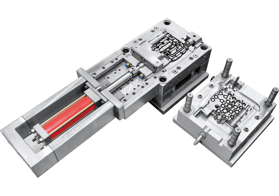
We are a professional Manifold Plate Injection Mold Manufacturer providing custom plastic injection mold Design and manufacturing for precision plastic components. This injection mold is designed for a manifold plate made from PA66-GF50, with a single-cavity structure, direct gating, and 1.2738 mold steel with a cavity hardness of HRC 33–38.
Our focus is not simply on manufacturing the mold, but on developing a Tooling solution that helps customers achieve stable injection molding, accurate part dimensions, reliable demolding, consistent quality, and repeatable production performance.
A manifold plate injection mold is a specialized plastic injection tooling system used to produce manifold plate components from thermoplastic materials.
The mold creates the required part geometry through a precisely machined cavity and core. During injection molding, molten plastic is injected into the mold cavity, where it fills the designed geometry, cools, solidifies, and is then ejected as a finished plastic component.
For engineering plastics such as PA66-GF50, the mold needs to account for material flow, shrinkage, cooling, dimensional requirements, and the influence of glass-fiber reinforcement.
A properly designed manifold plate injection mold helps address several common challenges in plastic component production.
The cavity and core define the final shape of the manifold plate. Precision machining and controlled mold assembly help maintain consistent dimensions from one molding cycle to another.
The direct gate provides a direct material entry point into the part. Gate location and material flow need to be considered during mold design to reduce filling problems and achieve a stable molding process.
PA66-GF50 is a glass-fiber-reinforced engineering plastic. Its molding behavior differs from that of unfilled plastics. Mold design therefore needs to consider material shrinkage and fiber reinforcement when determining cavity dimensions and processing conditions.
The ejection system must release the molded component without causing excessive deformation, sticking, or damage to critical surfaces. Ejection locations are selected according to the part geometry and structural requirements.
This example uses a HASCO standard prototype tooling configuration, making it suitable for prototype validation and early-stage production evaluation before moving toward higher-volume tooling when required.
The mold design starts with the actual molded part rather than the mold structure itself. We evaluate the customer's product geometry, material, tolerances, surface requirements, and expected production conditions before determining the tooling structure.
We review the 3D model or 2D drawing to identify:
Overall dimensions
Wall thickness
Deep or narrow features
Ribs and bosses
Draft angles
Critical dimensions
Parting line requirements
Potential undercuts
Ejection areas
This analysis helps determine whether the existing part design is suitable for injection molding and whether modifications are needed before mold manufacturing.
After analyzing the part, the mold structure is developed around the required cavity and core configuration.
The design may include:
Cavity and core
Mold base
Parting line
Runner and gate
Cooling channels
Ejection system
Guide and alignment components
Inserts where required
For this manifold plate example, the tooling uses a single-cavity configuration.
The gating system determines how molten plastic enters the mold cavity.
This mold uses a direct gate, where the molten material is introduced directly toward the molded component. Gate location is evaluated according to the part geometry and expected material flow.
For PA66-GF50, material flow behavior and glass-fiber reinforcement are important considerations during the gating and cavity design stage.
The cavity uses 1.2738 steel with HRC 33–38 hardness.
Mold steel selection is determined according to factors such as:
Mold service requirements
Plastic material
Production volume
Wear conditions
Surface finish
Dimensional requirements
Prototype or production tooling requirements
The appropriate steel and hardness help provide a suitable working surface for repeated molding cycles.
Cooling has a direct influence on injection molding cycle time and part dimensional stability.
Cooling channels are positioned according to the cavity geometry to help remove heat from the molded component. For complex areas, the cooling design needs to balance effective heat removal with the available space inside the mold.
Once the plastic component has cooled and solidified, it needs to be removed from the cavity.
The ejection system is designed around the product geometry to distribute ejection force appropriately and minimize deformation or visible marks on important surfaces.
Our typical tooling workflow includes the following stages:
Customer Drawing / 3D CAD Data
↓
Part & Moldability Analysis
↓
DFM Review
↓
Mold Structure Design
↓
Gate & Runner Design
↓
Steel Selection
↓
CNC Machining
↓
EDM / Precision Machining
↓
Mold Assembly
↓
Mold Inspection
↓
Trial Injection
↓
Sample Evaluation
↓
Mold Adjustment
↓
Final Mold Validation
This process allows potential issues to be identified progressively rather than waiting until the final molding stage.
Customers can provide a 3D CAD model, 2D engineering drawing, or product sample. Our engineers use the available product information to evaluate moldability and tooling requirements.
Design for Manufacturing analysis helps identify potential problems related to draft angles, wall thickness, parting lines, undercuts, gate positions, ejection, and material flow.
After the DFM stage, the mold structure is designed according to the part requirements. Cavity layout, gating, cooling, ejection, and mold base configuration are determined at this stage.
The mold components are manufactured using appropriate machining processes such as CNC machining and EDM according to the required geometry and tolerances.
Machined components are assembled and checked for alignment, movement, fitting, and overall mold function.
The completed tool undergoes trial injection to evaluate the molded sample. The trial process can help identify issues related to filling, flash, shrinkage, dimensional accuracy, ejection, and surface appearance.
If the trial sample does not meet the required specifications, the tooling can be adjusted according to the identified issue before final validation.
PA66-GF50 is a glass-fiber-reinforced nylon material used where higher mechanical performance is required compared with standard unfilled plastics.
However, the addition of glass fiber also affects the injection molding process. Mold engineers need to consider:
Material flow
Mold shrinkage
Fiber orientation
Dimensional stability
Mold wear
Gate location
Cooling conditions
Processing temperature
For this reason, the mold cannot be designed only according to the external shape of the part. The plastic material and molding behavior must also be considered during tooling development.
Before delivery, the mold can be checked through multiple stages of inspection and validation.
Critical mold components are checked for dimensions, fitting, and machining quality.
The assembled mold is inspected for proper alignment, opening and closing movement, ejection operation, and component interaction.
Injection-molded samples can be evaluated for:
Dimensional accuracy
Part geometry
Surface appearance
Flash
Short shot
Sink marks
Warpage
Ejection performance
The inspection results provide a basis for mold adjustment and final tooling validation.
Every plastic component has different geometry, material, tolerance, and production requirements. Therefore, the injection mold should be developed according to the actual product rather than using a standard tooling configuration for every application.
We can provide customized manifold plate injection molds based on:
3D CAD files
2D drawings
Product samples
Plastic material specifications
Dimensional tolerances
Surface finish requirements
Prototype requirements
Production volume
Customer tooling standards
Whether the project requires a prototype tool for design validation or a production-oriented custom plastic injection mold, the tooling structure can be developed according to the specific application.
A high-quality injection mold is the foundation of stable plastic injection molding. By combining part analysis, DFM, mold design, precision machining, proper material selection, trial molding, and tooling optimization, we help customers turn plastic component designs into repeatable molded parts.
If you have a manifold plate drawing, 3D CAD model, plastic material specification, or existing sample, send us your project requirements. Our engineering team can evaluate the part and develop a suitable custom injection mold solution for your application.
Base Cover is a practical molded component developed for projects that require stable structure, clean surface performance, and reliable production consistency. As a part produced through a professional injection mold solution, Base Cover is suitable for customers who need efficient development from sample evaluation to production implementation.
In many product development projects, proto mold plays an important role in confirming structure, appearance, and molding feasibility. After verification, the project can move smoothly into rapid injection molding, followed by formal plastic molding and plastic injection molding for regular production. This makes Base Cover an ideal choice for customers who want a balanced solution between development speed and production reliability.
This project uses 2 Drop YUD0 Manifold with Hot Tip Or Open Nozzle, which supports practical molding requirements and helps improve the overall adaptability of the mold design for Base Cover production.
The Base Cover mold is designed for stable molding performance and efficient project management. It supports a clear workflow from proto mold development to final plastic injection molding, making it suitable for product teams that require both flexibility and consistency.
With 2 Drop YUD0 Manifold with Hot Tip Or Open Nozzle, this injection mold solution is built to support practical molding needs and smooth part formation. The overall mold design reflects the value of combining rapid injection molding capability with dependable plastic molding execution, helping customers manage development and production more effectively.
Part Name: Base Cover
Type of Gate: 2 Drop YUD0 Manifold with Hot Tip Or Open Nozzle
Mold Dimension: 700500611 mm
Mold Weight: 1600 kg
Trial For Shipment: 3 times
Choosing our Base Cover solution means choosing a project approach that supports both early verification and later production. From proto mold to formal injection mold manufacturing, we focus on practical execution, stable process planning, and efficient communication.
For customers who need faster response during development, rapid injection molding helps shorten the path from idea to sample confirmation. After that, the project can move into consistent plastic molding and plastic injection molding, making the overall process more organized and easier to control.
Our goal is to provide a Base Cover mold solution that supports real project needs, improves development efficiency, and helps customers build confidence in every stage of production.
Base Cover can be used in projects that require molded housing parts, support covers, protective structural components, or base-related plastic parts. It is suitable for development programs that begin with proto mold evaluation and later transfer to production through rapid injection molding and formal plastic injection molding.
This kind of Base Cover project is also suitable for customers who want a clear injection mold solution with complete tooling information and practical gate design. In product categories where plastic molding quality and production continuity are important, Base Cover provides a dependable molding option.
Base Cover is a molded plastic part developed through an injection mold process. It is commonly used in projects that require a stable outer cover or structural base component.
Yes. Base Cover is suitable for proto mold development, especially for projects that need sample validation before moving to mass production.
Yes. This Base Cover project can be used in rapid injection molding workflows, helping shorten development and confirmation time.
The production route includes plastic molding and plastic injection molding, based on the provided mold design and tooling structure.
The gate system used in this injection mold project is 2 Drop YUD0 Manifold with Hot Tip Or Open Nozzle.
The Base Cover project completed 3 times of trial for shipment.