


 English

Products
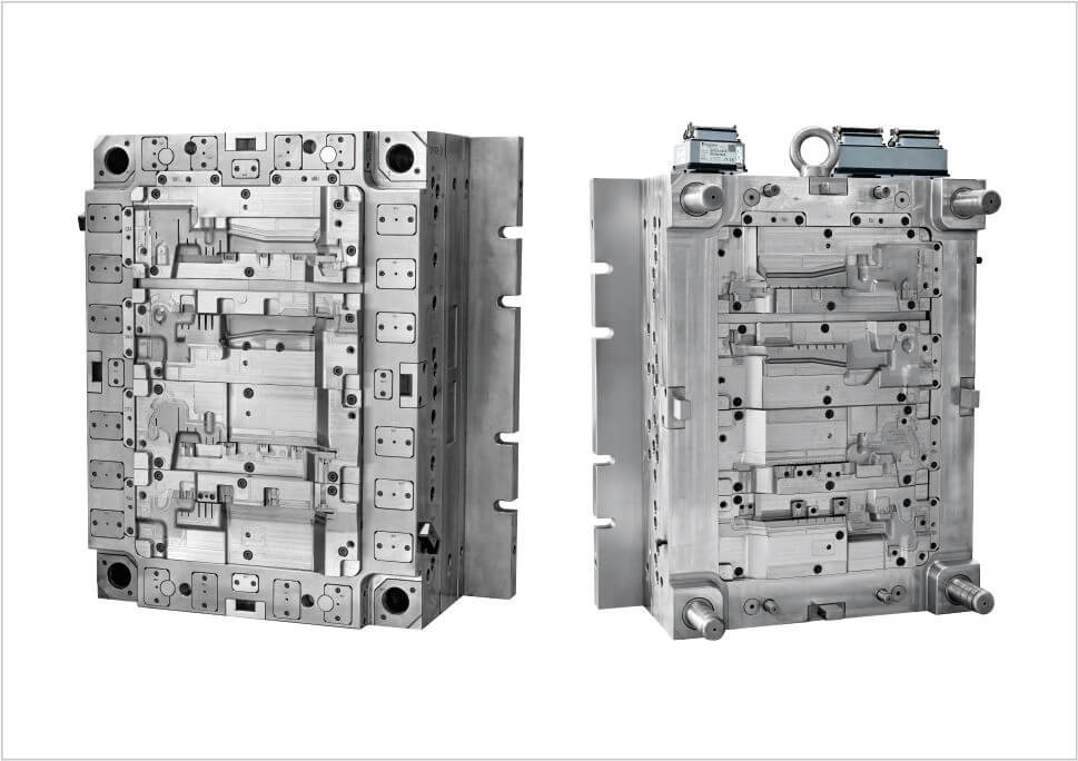
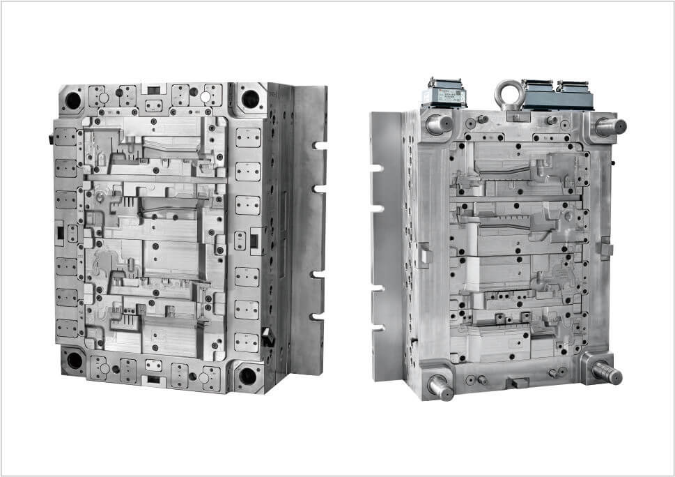
The LU LUFTFUEHRUNGSSEGMENT MI LI (AMG) is an automotive airflow management component produced using 2K injection molding. The German term “Luftführungssegment” refers to an air guide or airflow guide segment, indicating a functional plastic component Designed to guide and control air movement within a vehicle.
This Tooling is developed for a Mercedes-AMG vehicle application and combines PP-TD20 with TPE 75A in a two-component molding process. The tooling uses a 1+1+1+1 2K mold configuration with 8 pcs Synventive valve gates directly on the part.
The cavity steel is 1.2738HH with HRC 33–38 hardness, and the mold follows the HASCO standard.
An automotive air guide segment is a functional vehicle component used to direct, distribute, or control airflow within a designated area of the vehicle.
Unlike a purely decorative trim component, an air guide is designed around airflow management. Its geometry may contain curved surfaces, channels, ribs, partitions, locating features, or interfaces with adjacent components. The exact location and function depend on the vehicle architecture and OEM design.
In vehicle applications, airflow guide components may be used in areas such as front-end air management, cooling-related structures, engine-compartment airflow, underbody airflow control, or other systems where air needs to be directed along a defined path.
The primary purpose of an air guide component is to help control where air goes and how it moves through a vehicle system.
Guiding Airflow: Directs air toward the intended area.
Separating Air Paths: Helps keep different airflow routes from interfering with each other.
Improving Air Distribution: Supports more controlled airflow through the surrounding structure.
Supporting Vehicle Packaging: Provides a defined interface between airflow channels and neighboring components.
The available project information identifies the application as AMG, indicating a Mercedes-AMG vehicle program. The exact AMG model should be confirmed from the OEM drawing or project documentation before specifying a particular vehicle model.
2K injection molding, also known as two-component injection molding or two-shot molding, is used when a single component needs to combine two different materials or material properties.
For this project, the two specified materials are:
PP-TD20: Used as the primary rigid plastic structure.
TPE 75A: Used as a softer thermoplastic elastomer component.
This combination allows a single molded component to integrate rigid and flexible characteristics rather than manufacturing two separate pieces and assembling them afterward.
Depending on the final product design, the TPE section may serve functions such as flexible contact, sealing, cushioning, vibration reduction, or improved fitting with adjacent parts. The exact function should be determined from the approved OEM design.
The combination of a rigid engineering-oriented polypropylene material and a softer TPE material creates additional requirements for 2K plastic injection molding.
PP-TD20 provides the structural body of the component, while TPE 75A can provide localized flexibility where required by the design.
During mold development, the two materials need to be considered not only individually but also as part of the complete molding sequence. Material flow, interface geometry, cooling behavior, shrinkage, and dimensional stability can all influence the final product.
A 2K injection mold allows two materials to be molded into one integrated component through a controlled multi-stage process.
First Material Molding: PP-TD20 forms the primary rigid structure.
Tooling Transfer or Position Change: The molded first component is positioned for the second molding operation according to the mold design.
Second Material Injection: TPE 75A is injected into the designated area.
Final Cooling: The combined component is cooled and stabilized before ejection.
Integrated Part: The final component contains both rigid and flexible material zones.
The exact 2K mechanism depends on the mold structure, machine configuration, part geometry, and transfer method. The objective is to achieve accurate positioning and reliable bonding between the two molded materials.
The tooling specification states 1+1+1+1 (2K tool). This should not be interpreted simply as a conventional four-cavity mold.
The notation reflects the tooling arrangement used for the two-component molding process. In a 2K mold, cavity configuration needs to be considered together with the first-shot and second-shot molding stages.
For production validation, the relationship between each molding position, material stage, and final assembled geometry needs to be verified to ensure consistent two-component parts.
The tooling uses 8 pcs Synventive valve gates directly on the part.
Multiple valve gates can provide greater control over material entry into a relatively large or geometrically complex component. Instead of relying on a single filling point, the gate layout can help distribute molten material more effectively across different areas of the cavity.
For this type of automotive injection mold, gate placement can influence:
Filling balance
Injection pressure distribution
Weld-line position
Material orientation
Surface appearance
Part deformation
Cycle stability
Because the valve gates are positioned directly on the part, their locations must also be evaluated against the visible and functional areas of the component.
The cavity uses 1.2738HH steel with HRC 33–38 hardness.
For an automotive injection mold, cavity steel needs to maintain the designed geometry through repeated thermal and mechanical cycles. Steel selection also affects machining, polishing, wear resistance, dimensional stability, and mold maintenance.
The specified hardness provides a defined tooling condition for the cavity used in this 2K injection molding project.
Two-component automotive parts require coordination between both materials and both molding stages.
Material Compatibility: The two materials need to perform appropriately within the combined molding process.
Interface Design: The contact area between PP-TD20 and TPE 75A needs to be defined accurately.
Gate Layout: The valve gates need to support suitable material flow during each molding stage.
Cooling: Cooling needs to be considered for both materials and the complete mold structure.
Part Positioning: The second material must be injected at the correct location relative to the first molded section.
Ejection: The finished 2K component needs to be ejected without damaging the rigid or flexible sections.
Trial molding is particularly important for a 2K injection molding project because both material stages need to operate consistently.
The first stage should be checked for dimensional accuracy and stability before the second material is introduced. The final part is then evaluated to verify the position, coverage, and consistency of the TPE section.
Typical evaluation areas include:
PP-TD20 first-shot dimensions
TPE 75A position and coverage
Material interface quality
Part weight
Warpage
Flash
Short shots
Surface defects
Gate condition
Final assembly fit
An airflow component needs to maintain its designed geometry because deformation can influence the intended air path and the fit between adjacent components.
Quality control may therefore include dimensional inspection of key interfaces, visual inspection of the molded surfaces, verification of the TPE area, and functional checks related to assembly and airflow-related geometry.
For a 2K automotive injection molding project, quality control should also monitor consistency between the two material stages. A defect in either the PP structure or TPE section can affect the final component.
| Item | Specification |
|---|---|
| Part Name | LU LUFTFUEHRUNGSSEGMENT MI LI (AMG) |
| Part Type | Automotive Air Guide / Airflow Management Component |
| Mold Type | 2K Injection Mold |
| Cavity Configuration | 1+1+1+1 |
| Runner Type | 8 pcs Synventive Valve Gate Directly on the Part |
| Part Material | PP-TD20 / TPE 75A |
| Cavity Steel | 1.2738HH |
| Steel Hardness | HRC 33–38 |
| Mold Standard | HASCO |
Luftführungssegment is a German term meaning an air guide or airflow guide segment. It refers to a functional automotive component designed to guide or manage airflow within a vehicle.
It is an automotive airflow management component developed for an AMG vehicle application. Its function is to guide or control air flow through a designated area of the vehicle. The exact installation location depends on the OEM vehicle architecture.
The part uses PP-TD20 and TPE 75A. PP-TD20 provides the primary rigid structure, while TPE 75A provides a softer thermoplastic elastomer section.
2K injection molding allows two materials with different properties to be integrated into one component. This can eliminate separate assembly steps and combine rigid structural areas with flexible or sealing features.
The tooling specification is 1+1+1+1 for a 2K mold. Because this is a two-component tooling configuration, the notation should be understood in the context of the complete 2K mold arrangement rather than treated as a conventional four-cavity mold.
The mold uses 8 pcs Synventive valve gates directly on the part. The gate arrangement is designed to control material distribution and filling across the component.
The cavity uses 1.2738HH steel with HRC 33–38 hardness, with HASCO used as the tooling standard.
This AMG air guide segment demonstrates how 2K injection molding can integrate rigid PP-TD20 and flexible TPE 75A into one automotive component. The combination of material selection, direct valve gating, multi-stage molding, cavity design, cooling, and dimensional control is important for producing a stable functional part.
For OEM and Tier suppliers developing automotive air guides, air duct components, two-component plastic parts, and other precision 2K injection molded parts, mold design needs to be developed around the complete relationship between product geometry, materials, gating, molding sequence, and production requirements.
Explore custom 2K automotive injection mold manufacturing at Youking Mould.