


 English

Products
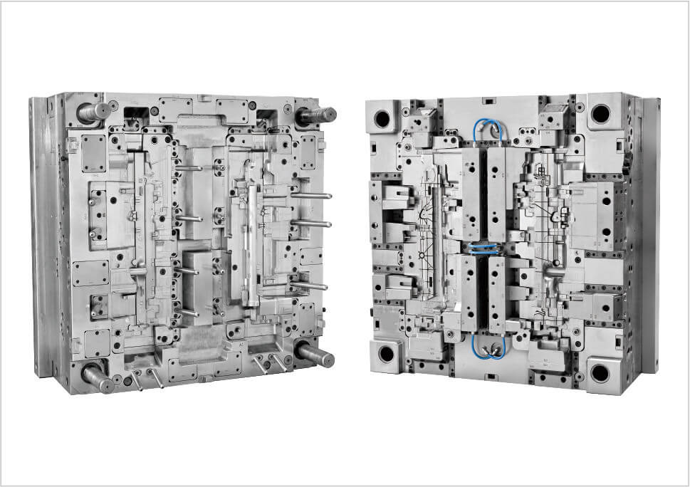
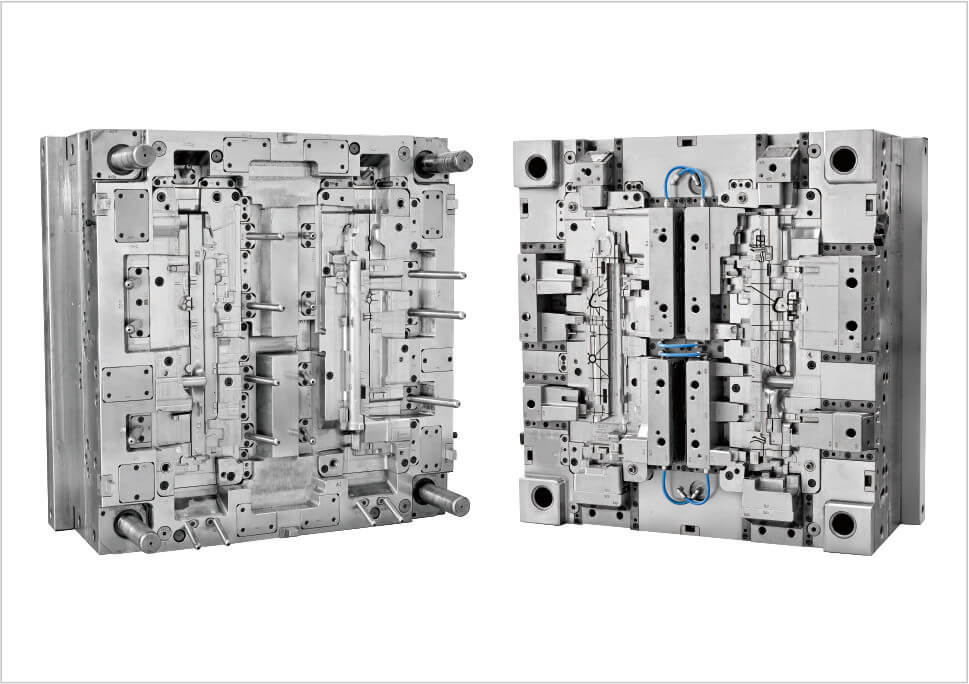
The TRAGRAHMEN RE (AMG) is a precision automotive plastic component developed for a Mercedes-AMG vehicle application. The German term “Tragrahmen” refers to a support frame or supporting frame, indicating a functional component Designed to provide structural support, positioning, or connection within a vehicle assembly.
The component is manufactured using PA6-GB30 through a controlled automotive injection molding process. The tooling uses a 1+1 cavity configuration with 4 pcs Synventive valve gates directly on the part. The cavity steel is 1.2738HH with HRC 33–38 hardness, with HASCO used as the mold standard.
Tragrahmen is a German engineering term that can be translated as “support frame” or “supporting frame.” In an automotive application, this type of component is generally designed to support, locate, connect, or stabilize other components within an assembly.
Unlike a purely decorative trim component, a support frame normally has a more functional role. Its geometry may include mounting points, locating features, ribs, attachment structures, and interfaces with neighboring components.
The exact installation position of this particular TRAGRAHMEN RE should be confirmed from the OEM drawing or vehicle assembly documentation. Based on the project information provided, it is associated with a Mercedes-AMG application.
A molded automotive support frame can perform several mechanical and assembly-related functions depending on the vehicle system in which it is installed.
Component Support: Provides a defined mounting structure for surrounding components.
Positioning: Maintains the relative position of connected components.
Load Distribution: Helps transfer or distribute mechanical loads through the assembly.
Assembly Interface: Integrates mounting holes, clips, locating points, or fastening structures.
Because support-frame components may have functional interfaces, dimensional accuracy can be more important than appearance alone.
The specified material is PA6-GB30, a glass-fiber-reinforced polyamide 6 material.
Compared with unfilled PA6, glass-fiber reinforcement can provide higher stiffness, strength, and dimensional stability, making reinforced nylon suitable for many demanding engineering applications.
For a structural or supporting automotive plastic component, these characteristics can be important because the part may need to maintain its geometry while exposed to mechanical loads and temperature variations.
However, glass-fiber-reinforced PA6 also requires careful control during plastic injection molding. Fiber orientation, material flow, shrinkage, cooling, and moisture management can all influence the final dimensions and mechanical behavior of the molded part.
The molding behavior of PA6-GB30 differs from that of standard unreinforced thermoplastics. During injection, the glass fibers tend to orient along the material flow direction, which can contribute to different shrinkage behavior in different directions.
For this reason, injection mold design needs to consider the interaction between gate position, flow direction, wall thickness, cooling, and critical dimensions.
Material Preparation: Nylon materials are sensitive to moisture and require appropriate drying before molding.
Flow Direction: Glass-fiber orientation can influence dimensional stability.
Wall Thickness: Sudden changes can increase shrinkage and warpage risk.
Cooling: Balanced cooling supports more consistent dimensions.
Ejection: The molded component should be ejected without deforming critical support features.
The tooling uses 4 pcs Synventive valve gates directly on the part. A direct valve-gate configuration provides controlled entry of molten PA6-GB30 into the cavity.
For an automotive support frame, multiple gates can be used to control filling across a relatively large or complex geometry. Gate positioning influences material flow, pressure distribution, weld-line locations, packing, and fiber orientation.
Because the gates are positioned directly on the component, their locations need to be evaluated carefully against functional surfaces, mounting areas, and any visible sections of the finished part.
When several valve gates are used, the filling pattern needs to remain sufficiently balanced so that the different areas of the cavity receive appropriate material and packing conditions.
An unbalanced filling pattern can lead to differences in pressure, shrinkage, fiber orientation, and part dimensions.
During precision injection molding, the relationship between gate location and part geometry should therefore be evaluated during mold development and trial molding.
The project specification indicates a 1+1 cavity configuration. This configuration provides two molding positions within the tooling arrangement.
The exact relationship between the two cavities should be determined from the product drawings and tooling layout. They may represent corresponding or mirrored components, depending on the OEM design.
During mold validation, the two molding positions should be compared for filling behavior, part weight, critical dimensions, warpage, and overall production consistency.
The cavity is manufactured from 1.2738HH steel with HRC 33–38 hardness.
For automotive injection mold manufacturing, the cavity material needs to maintain the required geometry under repeated thermal and mechanical loading.
The cavity steel selection also needs to support precision machining, surface preparation, dimensional stability, and long-term mold maintenance.
A support-frame component requires a mold design that considers more than external dimensions. Functional interfaces need to remain stable after molding so that the finished part can be assembled correctly.
Mounting Points: Hole and fastening positions must remain accurate.
Locating Features: Positioning structures need to be reproduced consistently.
Ribs: Reinforcing ribs need suitable draft and cooling conditions.
Wall Thickness: Large thickness differences can increase deformation.
Cooling: Uniform heat removal helps maintain dimensional stability.
Ejection: Ejection force should be distributed to protect functional structures.
Trial molding is used to verify the interaction between the mold, PA6-GB30 material, and injection molding process before production approval.
For a reinforced nylon component, trial evaluation should pay particular attention to dimensional stability, warpage, material flow, and cavity-to-cavity consistency.
Typical inspection items include:
Critical dimensions
Mounting-hole positions
Locating features
Part weight
Warpage
Flash
Short shots
Weld lines
Gate condition
Assembly fit
For a functional automotive plastic component, quality control should focus primarily on dimensional and functional consistency.
In addition to appearance inspection, critical dimensions should be monitored throughout production. This is particularly important for mounting and locating features because even small deviations can affect downstream assembly.
Process parameters such as injection speed, pressure, mold temperature, holding pressure, and cooling time should also be controlled within a stable process window.
| Item | Specification |
|---|---|
| Part Name | TRAGRAHMEN RE (AMG) |
| Part Type | Automotive Support Frame |
| Application | Mercedes-AMG Vehicle Application |
| Cavity Configuration | 1+1 |
| Runner Type | 4 pcs Synventive Valve Gates Directly on the Part |
| Part Material | PA6-GB30 |
| Cavity Steel | 1.2738HH |
| Steel Hardness | HRC 33–38 |
| Mold Standard | HASCO |
Tragrahmen is a German engineering term meaning “support frame” or “supporting frame.” In automotive applications, it generally refers to a functional frame used to support or position other components.
It is a functional automotive support frame made from PA6-GB30. The exact installation position and vehicle system should be confirmed from the OEM product drawing.
The tooling project is identified for a Mercedes-AMG (AMG) vehicle application. The specific AMG model is not identified in the available tooling specification.
PA6-GB30 is a glass-fiber-reinforced polyamide material selected for applications requiring increased stiffness, strength, and dimensional stability compared with unreinforced PA6.
The tooling specification indicates a 1+1 cavity configuration. The exact relationship between the two molding positions depends on the OEM product and tooling layout.
The mold uses 4 pcs Synventive valve gates directly on the part, allowing controlled material entry and helping manage filling and packing conditions.
The cavity uses 1.2738HH steel with HRC 33–38 hardness, with HASCO used as the mold standard.
The TRAGRAHMEN RE project demonstrates the requirements involved in molding a functional automotive support component from PA6-GB30. Gate design, glass-fiber material behavior, cavity accuracy, cooling, ejection, and dimensional inspection all contribute to the stability of the finished part.
For OEM and Tier suppliers developing automotive support frames, structural plastic components, PA6-GF injection molding parts, and other precision automotive plastic parts, the mold needs to be developed around the complete relationship between product function, material behavior, tooling structure, and production requirements.
Explore custom automotive injection mold manufacturing at Youking Mould.