


 English

News
Wed 10 , 2026
The most expensive way to discover a filling problem is to discover it on the trial report, after the steel has been cut, hardened and polished. mold flow analysis exists to move that discovery forward — to a point where changing the gate position costs an afternoon of engineering rather than a week of machining and a re-polish. Done properly it is one of the cheapest items on a Tooling project. Done badly it is a colourful picture that nobody acts on.
This guide explains what mold flow analysis actually predicts, when it is worth paying for and when it is not, what its limits are, and what you need to send to get a study you can make decisions from.
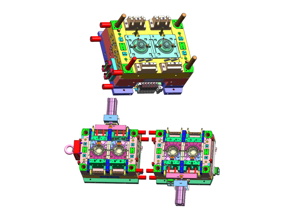
Mold flow analysis is a computer simulation of what happens inside the cavity when molten resin is injected into it. The part geometry, the runner and gate layout, the cooling channels and the proposed process settings are modelled together, and the software calculates how the polymer fills, packs and cools, and how the part will distort as a result.
The point is not the picture. The point is that the tool does not exist yet, so every decision the simulation informs is still free to change. Moving a gate, adding a rib, changing a wall thickness or re-routing a cooling line costs nothing at this stage and a great deal later. Our mold design and mold flow analysis stage exists precisely to run those changes before the first block of steel is touched.
A useful study answers a specific set of questions. If a mold flow analysis service sends you screenshots without a conclusion, you have been given graphics rather than analysis. The table below lists what a proper study reports and what decision each result drives.
| What the study reports | What it tells you | What you change as a result |
|---|---|---|
| Fill pattern and fill time | Whether every cavity fills at the same time, and where the flow front ends up | Gate position, gate size, runner balance |
| Short shot prediction | The thinnest or furthest region that may not fill at all | Wall thickness, gate size, material grade, machine tonnage |
| Weld line locations | Where two flow fronts meet — the mechanically weakest lines on the part | Gate position so that weld lines land in non-critical areas |
| Air trap prediction | Where air will be trapped and burn | Vent placement, gate position, flow balance |
| Pressure and temperature at the flow front | Whether the part can be packed before the gate freezes off | Gate size, runner Design, hold profile |
| Clamping force requirement | The tonnage the tool needs, and the projected area driving it | Machine selection, cavity count |
| Cooling analysis | Cavity surface temperature distribution and expected cooling time | Cooling channel layout, baffles and bubblers, cycle time |
| Warpage prediction | The likely direction and magnitude of distortion after cooling | Shrinkage allowance, cooling balance, rib and boss geometry |
| Cycle time estimate | A realistic cycle time to quote against, rather than a target | Cost per part, cooling design |
The most valuable of these is usually mold filling analysis combined with the weld line and air trap predictions, because those are the results that change the tool drawing. Warpage prediction is the hardest to trust absolutely and the most useful when it is right.
The practical question is when do you need mold flow analysis — because running a full study on every simple part is a waste of money, and skipping it on a difficult part is a false economy. The table below is the rule of thumb we use when quoting.
| Part or tool characteristic | Recommendation | Why |
|---|---|---|
| Simple, uniform wall, single cavity, one gate, non-visible part | Normally not needed | The design is forgiving; a trial will confirm it |
| Large flat panel or a part that must stay flat | Strongly recommended | Warpage is the risk and it is invisible until the part cools |
| Thin wall or a long flow path relative to thickness | Recommended | Short shots and high injection pressure are likely |
| Multi-cavity or family tool | Recommended | Cavity-to-cavity balance cannot be guessed |
| Multiple gates, or a hot runner system | Recommended | Weld lines and hesitation effects have to be placed deliberately |
| Visible or cosmetic surface, or a transparent part | Recommended | Weld lines, flow marks and gate blush all show |
| Structural part with strength requirements | Recommended | Weld line position determines where it fails |
| Tight dimensional tolerance (see our guide to what tolerance injection molding can hold) | Recommended | The shrinkage allowance in the tool depends on the analysis |
| Insert or overmoulded part, or a two-shot tool | Recommended | Two materials, two flow fronts, one interface |
| High annual volume where a one-second cycle difference matters | Recommended | Cooling optimisation pays back immediately |
A useful test before you commission a study: can you name the two or three dimensions or defects that would make the part fail? If you can, the study should be scoped to answer those specifically. If you cannot, the part probably does not need one yet.
Any honest discussion of injection molding simulation has to include what it cannot do, because the failure mode of these projects is over-trust.
It is only as good as the material data. Resin suppliers publish different grades of data for the same family. A study run on generic PP data for a part that will run in a glass-filled engineering resin is close to worthless.
It models the mould, not the machine. A simulation assumes an ideal injection unit. Real check rings, worn screws and undersized barrels change the result.
Warpage prediction carries real error. Trends are reliable, absolute values are not. Use it to compare two designs, not to promise a dimension.
It does not replace a trial. Simulation narrows the design space; the trial proves the tool. Our guide to what to check at an injection mold trial covers that side.
It does not fix a bad part design. If the wall thickness varies by 2:1, the analysis will simply tell you that it does.
The right way to read a study is as a risk-reduction tool: it removes the designs that definitely will not work, and it ranks the ones that remain. It does not certify that a design will work.
This is where mold flow analysis before cutting steel earns its cost. Typical findings and the resulting changes look like this:
Unbalanced fill in a multi-cavity tool. The runner is re-sized or the cavity layout is mirrored, so all cavities fill together instead of the nearest one filling first.
A weld line across a structural rib or a cosmetic surface. The gate is moved, or an additional gate is added, to relocate the weld line into a non-critical area.
Air traps at the end of fill. Vents are added to the tool drawing before the cavity is machined, instead of being spark-eroded after the first trial.
Excessive warpage from uneven cooling. Cooling channels are re-routed, baffles or bubblers are added to the core, or the cooling layout is made symmetric.
Gate freeze-off before packing is complete. The gate is enlarged, or the gate type is changed — a common finding on parts with a thick section remote from the gate.
Shrinkage allowance. The analysis informs the actual scaling factor applied to the cavity, rather than a value taken from a table.
Every one of those changes is cheap in the design phase and expensive afterwards. That asymmetry is the entire argument for running the study.
A study is only as specific as its inputs. For a plastic part mold flow analysis you can act on, send:
The 3D part file in STEP or IGES at the revision you intend to manufacture, not a concept model.
The resin grade — supplier and grade name, and whether it is filled, flame-retardant or transparent.
The wall thickness range, or a drawing showing the nominal wall and where it changes.
The intended cavity count and, if you have a preference, the gate location or the feed side of the part.
The annual volume and the cycle time you are targeting, so cooling is optimised for the right point.
Any cosmetic or functional restrictions: which faces are visible, which dimensions are critical, where the part is loaded in service.
The last item is the one most often missing, and it is the one that decides whether a weld line in a particular place matters. A supplier who asks you for it is a supplier who intends to act on the result.
Youking Mould has built custom injection molds in Dongguan since 2006, with mold design, mold flow analysis, tooling and injection production on the same site. Because the people who run the analysis are the people who cut the cavity, the findings become a tool change rather than a document — the gate is moved in the design, the vent goes into the drawing, and the cooling layout is corrected before the block is machined.
You can see the stage on our injection mold design page, and what happens to the steel afterwards on our custom injection mold tooling and precision mold components pages. If warpage is your specific worry, our guide to why injection molded parts warp goes through the causes in more detail.
Mold flow analysis is worth paying for when a wrong decision would be expensive — a large flat part, a multi-cavity tool, a tight tolerance, a visible surface or a structural part. It is not worth paying for on a simple part where the trial will answer the same question. The value is not in the simulation images; it is in the design changes they trigger while the steel is still a block of un-machined material.
If you have a part in development and you are not sure whether it needs a study, send us the 3D file, the resin grade and the two or three dimensions that worry you. Our engineering team will tell you whether a mold flow study is justified, what it would change, and what the tooling would look like either way.
We attach great importance to the customers' demands for product quality and rapid production.
We always believe that meeting the customers' needs is the realization of our value!